The Impact of Non-Standard Cabling on Image Quality in Analog and IP Surveillance Cameras
This article examines how improper cabling affects image quality in analog and IP camera systems and outlines standards-based installation practices, preventive measures, and troubleshooting.
خلاصه تخصصی مقاله
This article examines how improper cabling affects image quality in analog and IP camera systems and outlines standards-based installation practices, preventive measures, and troubleshooting.
موضوعات اصلی: Cabling، cable، Quality، Image، noise، cables
The Impact of Non-Standard Cabling on Image Quality in Analog and IP Surveillance Cameras
In CCTV installations, cabling acts as the backbone of the network. If this part is not implemented to standard, even the most advanced cameras and recorders may not deliver the desired results. Standard cabling ensures images are transmitted to the control center without quality loss, noise, or delay.
Why is standard cabling important?
- Stable image quality Nonstandard or low-quality cables introduce noise, parallel lines, and reduced resolution.
- Data transfer reliability In IP cameras, cable quality directly affects transfer speed; Cat6 and Cat6a can support up to 10 Gbps.
- Increased equipment lifespan Poor cabling increases heat and load on recording devices and switches.
- Lower maintenance costs Proper cabling reduces recurring issues and service calls.
- Security standards compliance Standard cabling improves resilience to EMI.
According to a report by TIA/EIA in the standard TIA-568-C.2
Adhering to structured cabling principles in surveillance systems not only ensures image quality but also significantly facilitates management, maintenance, and future network expansion.
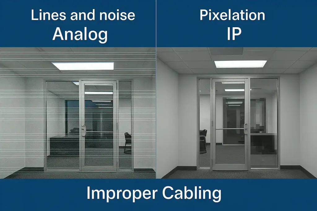
Signs of image degradation due to nonstandard cabling
1. Lines or color noise on image (Analog cameras)
In analog cameras, the most common issue appears as parallel lines or color noise on the image. This is typically due to using low-quality coaxial cables or unprofessional terminations such as poor-quality BNC connectors. Such issues can render images unusable even in the short term.
2. Pixelation or frame drops (IP)
In networked systems, if standard cables (Cat5e/Cat6) are not used or the length exceeds the allowed limit, data is not transmitted properly. This shows as pixelation, frame drops or momentary freezes; packets arrive incomplete due to noise or interference.
3. Display delay or momentary dropouts
Another sign is delay or lag in live display, especially in IP cameras requiring high bandwidth. Momentary dropouts are usually caused by using low-quality cables or nonstandard terminations.
Causes of Nonstandard Cabling in Surveillance Systems
One of the main factors causing image quality degradation is nonstandard cabling. While many users think only the camera or the DVR/NVR determines image quality, the type of cable, installation approach, and environmental conditions are equally important. Here we review the main causes:
1. Use of counterfeit or low-quality cables
Counterfeit cables often lack pure copper cores and use weak alloys or aluminum with copper coating. This increases resistance and adds noise.
2. Cable length beyond standard
Each cable has a standard transmission range (for example RG59 coax up to about 300 meters, CAT6 up to about 100 meters). If length exceeds, signal weakens and image quality degrades.
3. Unprofessional terminations
Incorrect terminations or poor soldering create high-resistance points along the path, causing signal loss, noise, and potential damage.
4. Lack of shielding and proper grounding
Shielding and grounding help reject EMI; without shield or ground, cables become susceptible to electromagnetic fields and environmental noise.
5. Cabling near sources of noise (high-voltage power lines, industrial equipment)
If cables pass near high-voltage lines or industrial equipment, EMI coupling increases and noise enters the image.
Preventive measures to avoid image degradation
| Measure | Description |
|---|---|
| Use standard cables (RG59 or CAT6) | Quality cables with shielding reduce noise and stabilize transmission. |
| Respect maximum cable length | Coax: 90 m or less; Network: 100 m or less; longer lengths may require boosters. |
| Professional terminations | Use proper tools to terminate RJ45 or BNC connectors. |
| Shielding and grounding | Reduces EMI and protects against high voltage sources. |
| Cabling separated from power lines | Route should avoid power lines and industrial equipment to reduce induced noise. |
Troubleshooting and improving image quality
| Problem | Proposed solution |
|---|---|
| Noise or lines on image (Analog) | Check cable quality and replace poor cable; ensure proper BNC connection. |
| Pixelation or frame drops (IP) | Test network speed; use a gigabit switch; reduce network cable length. |
| Momentary image dropout | Check power supply and camera power; verify connector and switch connections. |
| Delay in live display | Increase bandwidth or use CAT6 or higher cable. |
| EMI from power | Change cable path and use shielded cable or proper grounding. |
Testing and diagnosing cabling issues
To confirm whether image quality issues are caused by nonstandard cabling, use the following methods
- Use of network or coaxial testers
- For IP cables (Cat5e/Cat6), a network tester shows whether each wire is punched correctly.
- For analog systems, a coaxial tester can assess the signal quality and locate faults.
- Cable resistance check (Ohm test)
- Use a multimeter to measure electrical resistance of the cable.
- Standard cables have low resistance; abnormally high resistance indicates a fault or low-quality cable.
- Practical test with a healthy camera and short standard cable
- Connect the same camera with a short, good cable.
- If the issue is resolved, the main cabling is likely at fault and needs correction or replacement.
Preventive checklist to avoid degradation
- Choose standard and high-quality cables (Cat6 for IP and RG59 or RG6 with quality for analog)
- Respect maximum cable length (100 m for network, 300 m for RG59; longer with amplifier)
- Professional terminations with standard tools
- Use shielded cable and proper grounding in noisy environments
- Separate network and video cabling from high voltage power lines or industrial noise sources
- Use conduit, tubing, and cable protection to prevent physical damage
- Test cabling before system commissioning with a tester or multimeter
- In large projects, use standard PoE switches or separate power supplies to reduce noise
- Promptly replace worn or damaged cables
- Consult expert guidance for camera installation to ensure proper execution
Conclusion
Standard cabling is the backbone of a stable surveillance system. While choosing good cameras and DVR/NVR is important, without proper cabling the entire system may suffer quality loss. Using quality cables, following installation practices, and performing periodic tests can address most image-related issues. For organizational or sensitive projects, it is advisable to engage professionals for installation to guarantee image quality and system security.
1. Why is my analog camera image full of lines and noise?
Likely your cabling is not of adequate quality or passes near noise sources.
2. Does long cable length affect quality?
Yes. For coaxial cables longer than about 90 m and network cables longer than about 100 m, quality can degrade and delay may occur.
3. Is shielded cable always necessary?
No, but in industrial environments or places with strong electrical noise sources, shielded cabling is recommended.
To assess the resilience and security of this infrastructure, study the network support guide as well.
برای ارزیابی پایداری، امنیت و نگهداری این زیرساخت، راهنمای پشتیبانی شبکه را نیز مطالعه کنید.